Router Table - Build
This is the second part of my January 2022 project to make a router table for my Triton MOF001 using a Kreg table insert. If you haven’t already, head over to part 1 for the design stage of this project.
Building the Top
Slots for the T-Slots were cut using a 19.1mm (¾ inch) router bit with wooden guides attached to the top using double-sided tape. Once the slots were cut, the ends were squared off using a chisel and the slots mounted with the supplied screws. The only small issue was that the screws were longer than the wood underneath the slots so they poked out the other side. This was something I was expecting to happen as there is only 8.5mm beneath the slots (18mm total minus 9.5mm for the slots). A few minutes with a cutting disc on a Dremel rotary multi-tool followed up by a quick sanding was enough to remove the offending spikes.
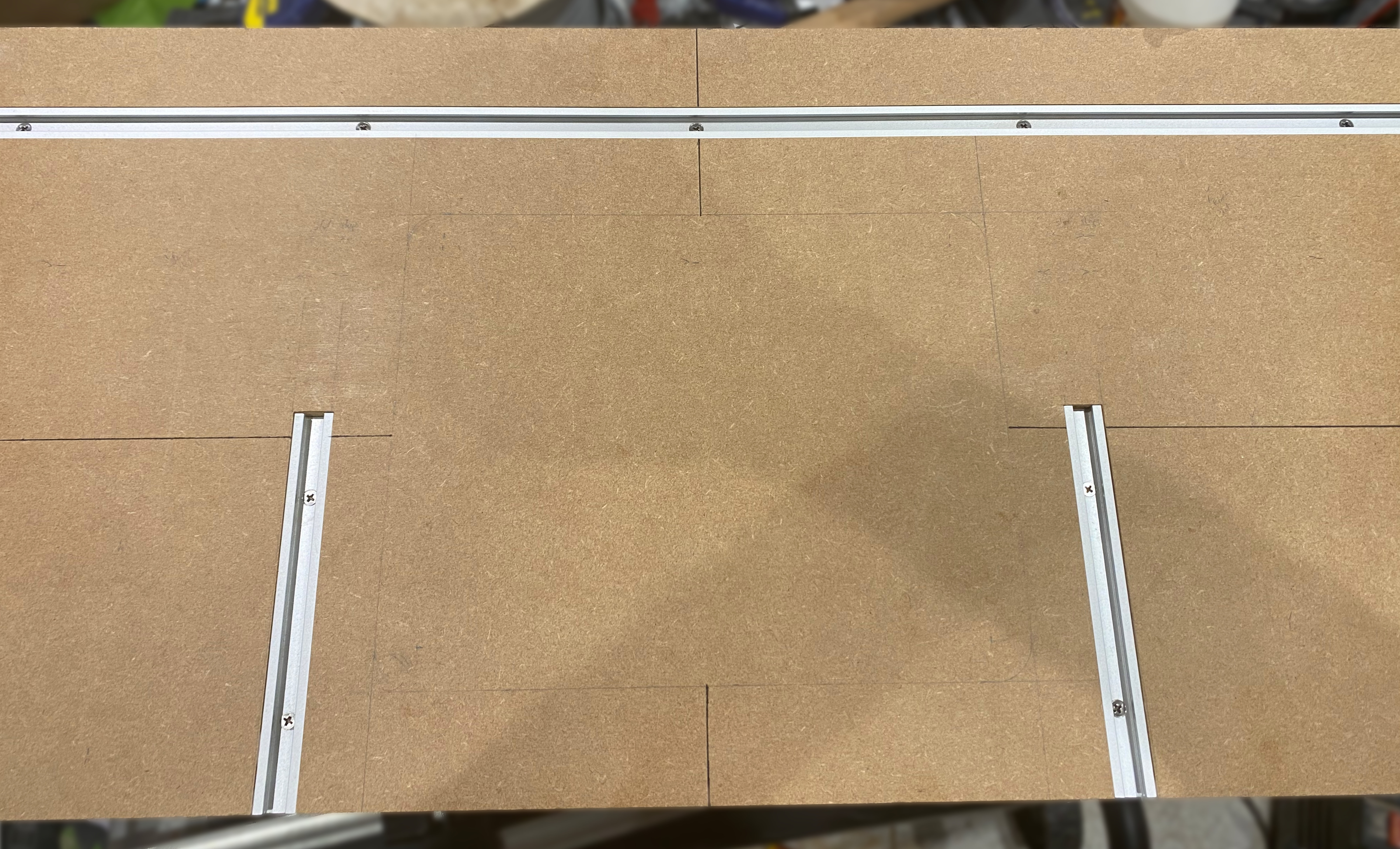
Two strengthening ribs were attached to the underside of the top to prevent sagging and a reinforcing section was added underneath the area that the insert place was going to be installed. Once these were added it was time to start cutting out the opening for the router using more guides taped to the top, a guide-bushing and a long (12.7x63mm) router bit that would handle the combined thickness of three sheets of 18mm MDF (guide + top + reinforcement).
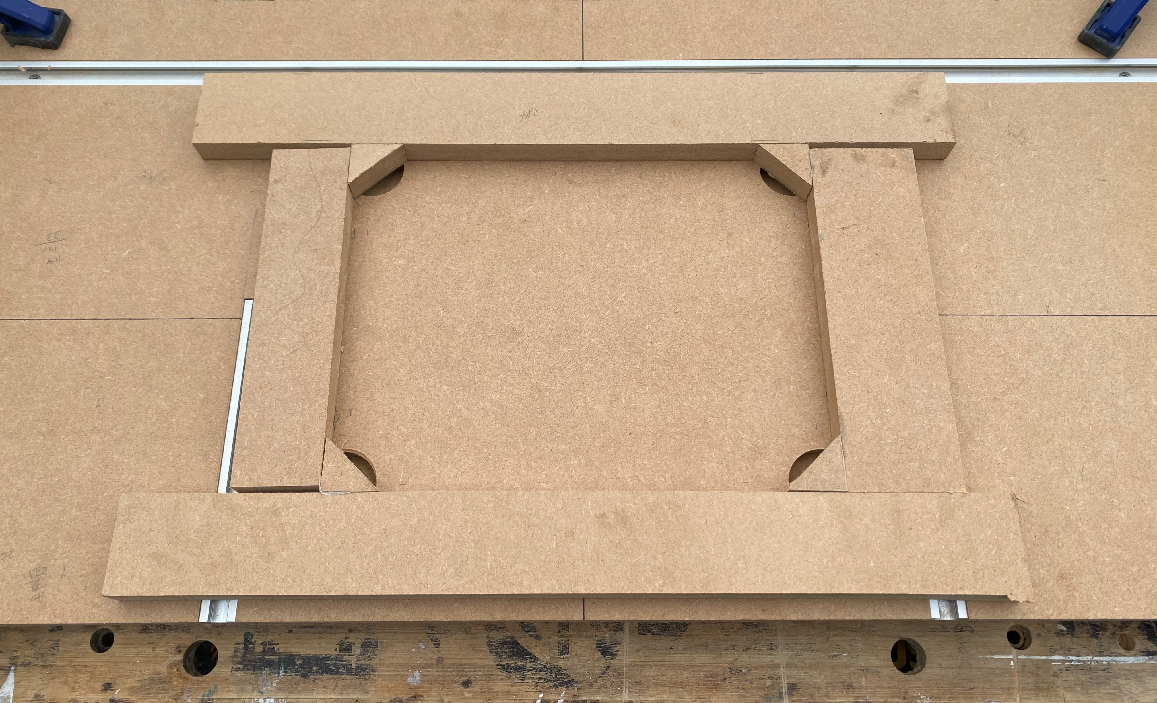
After the opening was routed it was time to reposition the guides and start routing out the recess for the insert plate, this time with a shorter (12.7x38.1mm) bit. A second guide was placed over the opening to support the router and prevent it tipping into the opening - the Triton MOF001 is a great router for big work, but it is heavy which makes these operations harder. The corners of the recess were made before the opening using a 19mm (¾ inch) forstner bit on a drill press, and I eyeballed the start & stop points when routing the recess.
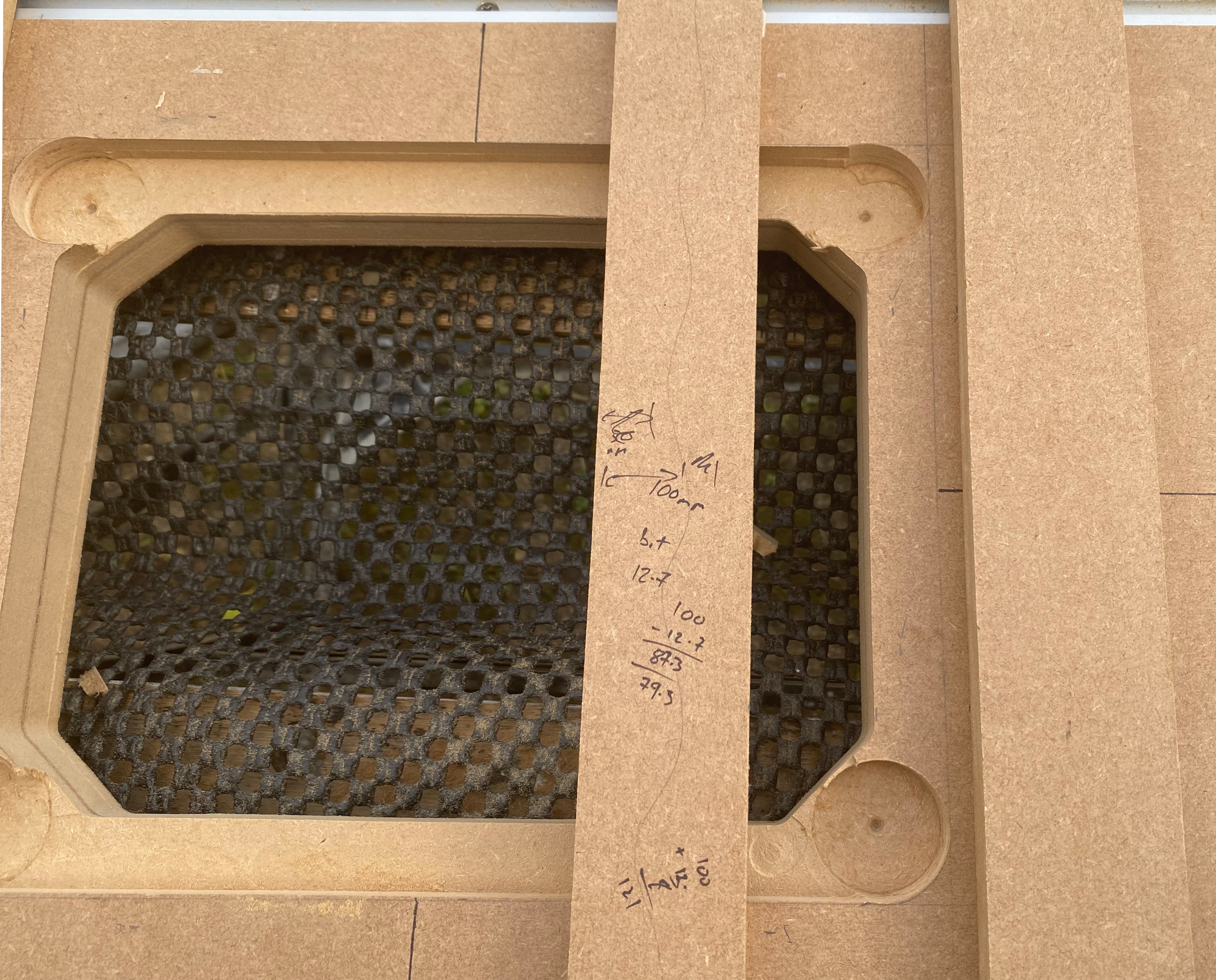
With the recess fully routed it was time to test fit the mounting plate, this required a couple more passes with the router to widen the recess slightly but resulted in a snug fit. The plate sits about 2mm below the surface of the table but this will be easy to correct with a couple of shims.
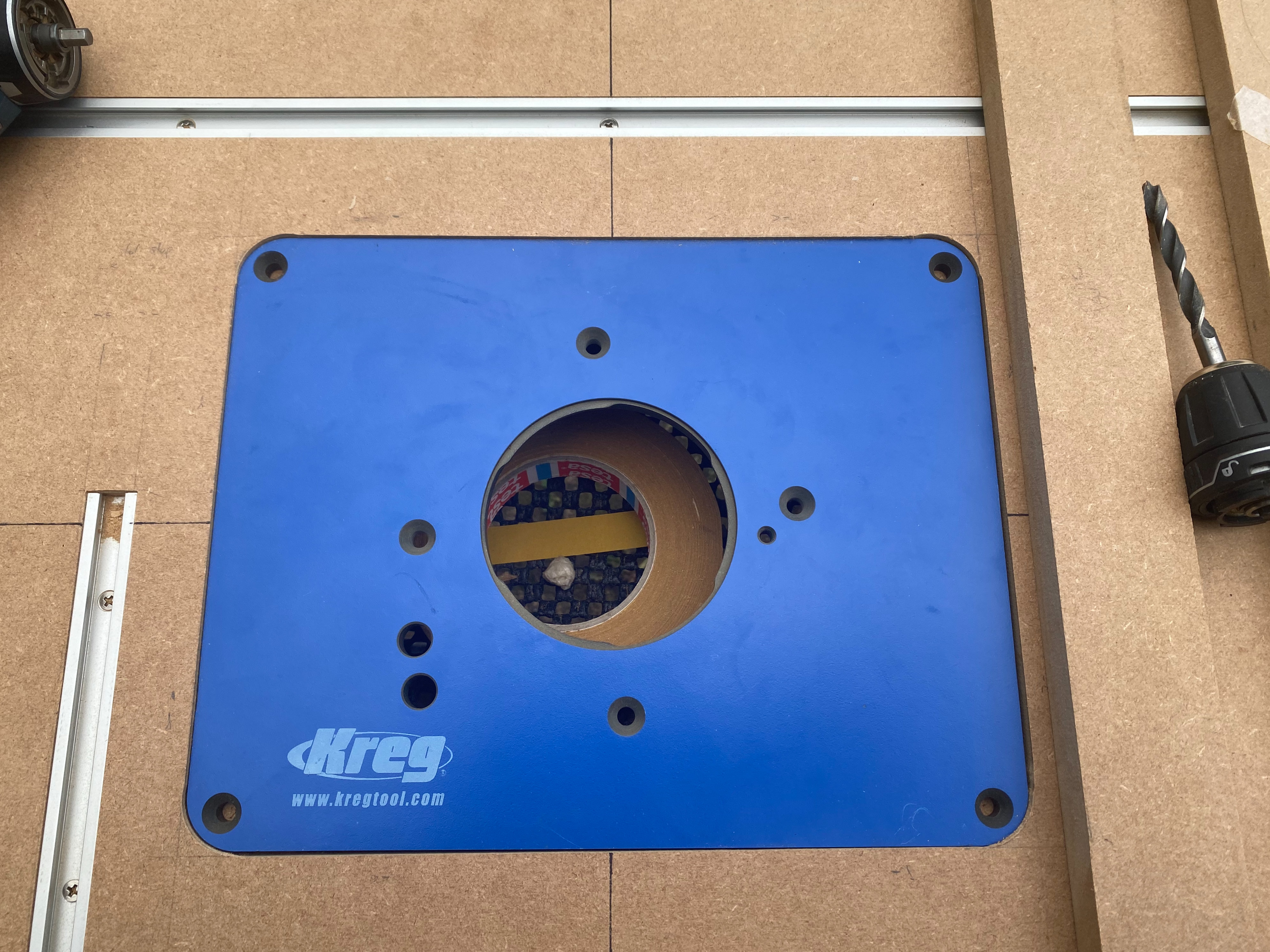
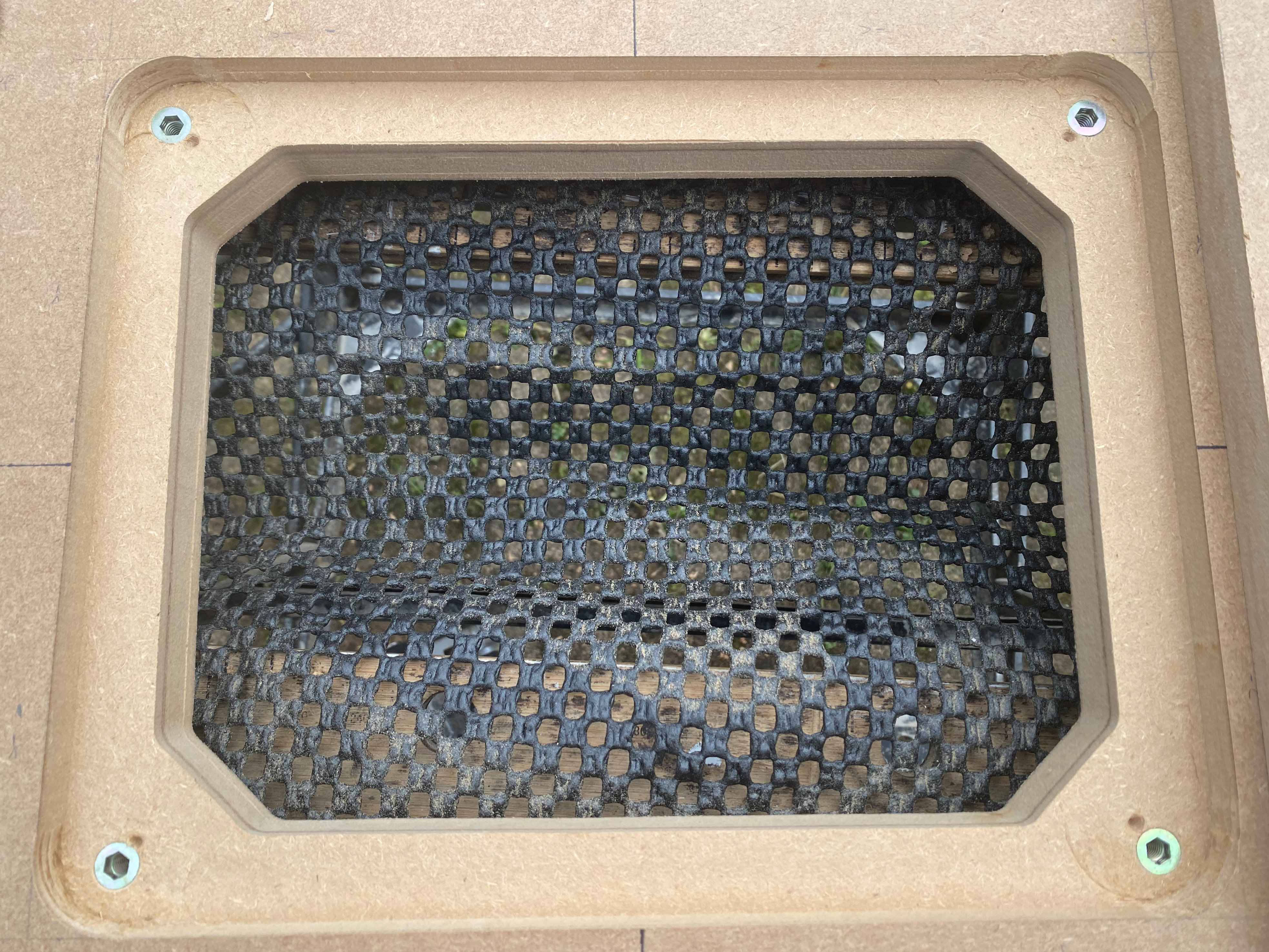
Using the mounting plate in-place the fixing holes could be marked, drilled and threaded inserts installed:
Adding the Legs
With the top completed the legs could be assembled with loose tenons[1] and then attached to the top. It took a couple of attempts to attach the legs to the top as I made the schoolboy error of referencing the wrong face when cutting the slots in the bottom of the top. Thankfully the incorrect slots were only about 4mm off and are covered by the top of the legs. At least this time I didn’t forget to change the depth of the DOMINO and plunge all the way through the top surface!
Making the Fence
With the main table completed it was time to start work on making the fence which was constructed in a similar manner to the main table with loose tenon joints holding everything together.
Routing out the T-Slot on the front of the fence was a great opportunity to test out the table and made it much easier than the T-Slots on the main table. The base part of the fence on its own worked well as a temporary fence even without being able to have a featherboard to hold the piece down. The only thing that was disappointing was the dust collection (or lack thereof), even with a powerful shop vac attached to the dust port of the router it wasn’t enough to clear the routed slot of sawdust. I’m not sure whether this was due to the opening on the insert plate being too small for the bit used or something else, but I have plans to revisit this in the future.

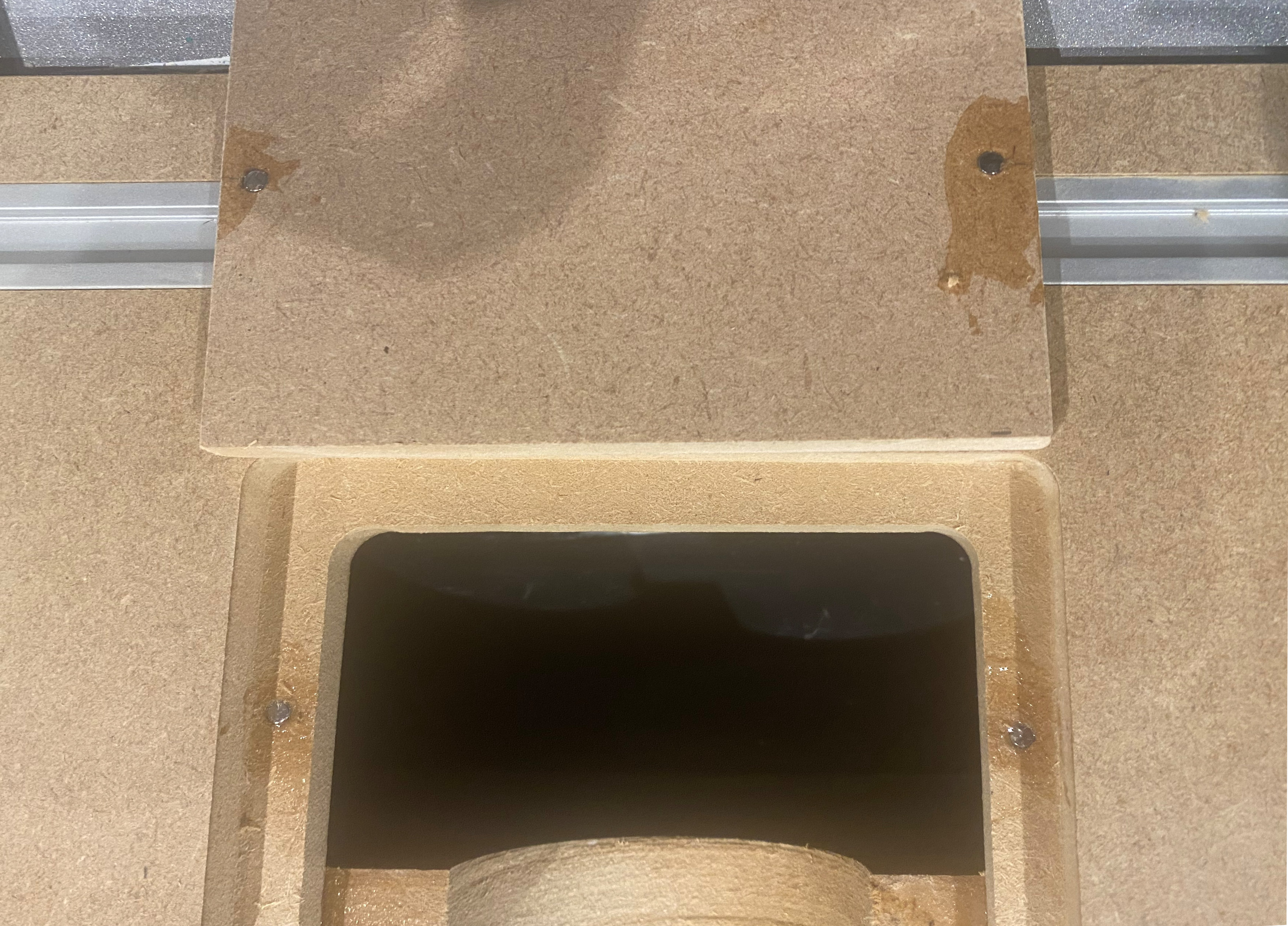
To accommodate different sized router bits, a large opening was made in the centre of the fence and a pair of removable insert plates made. These plates were constructed from 9mm MDF and attached to the main fence using 4mm diameter neodymium magnets that were secured using two-part epoxy. Currently both of the plates are solid but they can be easily modified for whatever type of bit is being used and replacements can be be quickly made from offcuts of MDF.
Finishing & Final Thoughts
The top surface of the table and the reference side of the fence were both treated with two coats of Briwax Original wax to give it a smooth finish. The rest of the table and fence were both left untreated as this is a shop tool and will get knocked about a lot.
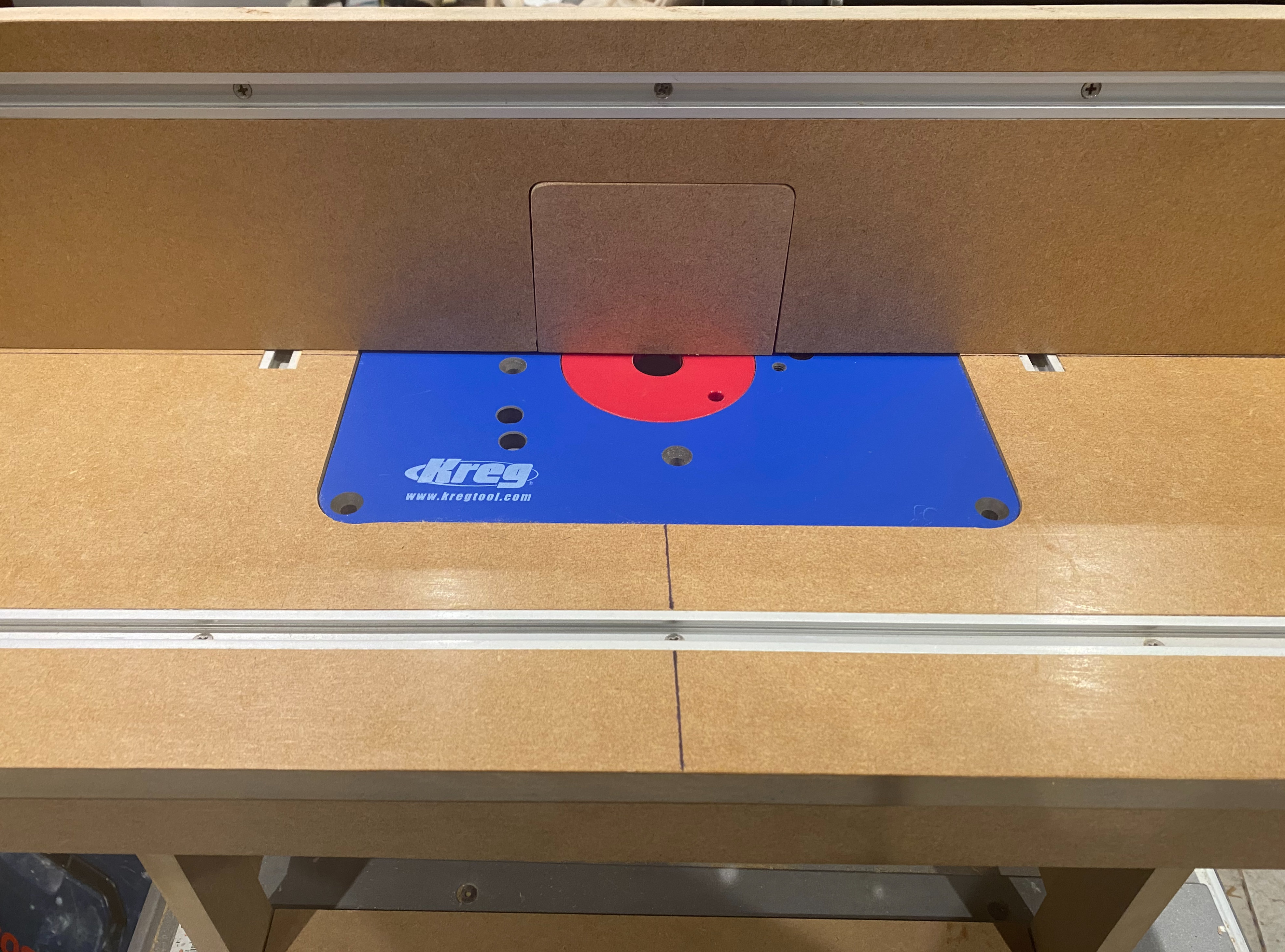
The final table turned out really well and very close to the initial design (see below). I still need to add an NVR[2] switch and pass-through power cable to improve safety, this will get mounted in to one of the legs where it can be easily accessed. Another area for improvement is to add a dust extraction hood to the fence, this will probably be 3D printed and might become a future project on this blog.
One unexpected challenge while making the table was the suitability of the MDF that I used. This was left over 18mm MDF from some shelving I’d previously built which turned out to be rebranded Medite Trade. While this worked well for making shelves, it didn’t machine well and required a lot of sanding to get a satisfactory finish. For these reasons I will be avoiding this product in the future for projects that involve routing or shaping.
Changes from the Original Design
There were two areas where I decided to tweak the design during construction. The first was increasing the the size of the supporting recess underneath the insert from 9.4mm (¼ inch) in each direction to 20mm. This makes it slightly harder to get the router in but should make it stronger.
The second change was the addition of braces between the pairs of legs near the top. These were added to make it easier to align everything during assembly and to resist shear forces along the length of the table. They are very close to the plunge handles of the router but as they don’t make contact all is good.
Next Project
The project for February will be 3D printing and painting a T-Rex Skeleton.
Loose tenon joints made using a Festool DOMINO and 5x30mm DOMINO dowels. ↩︎
No-volt-release switch. These automatically reset if the power is disconnected to ensure that the tool doesn’t unexpected start when reconnected. They also tend to include a big red emergency stop button. ↩︎
